|
ADMIN
Administrator
Inregistrat: acum 17 ani
Postari: 114
|
|
Smallest GPS Network for Tallest Building
Core Wall Survey Control System for High Rise Buildings
Joël van Cranenbroeck
Leica Geosystems AG
Heinrich-Wild-Strasse CH-9435 Heerbrugg
SWITZERLAND
Douglas Hayes
Burj Dubai Tower
Samsung Besix Arabtch JV
P.O. Box 102739
DUBAI UAE
Ian Sparks
Connell Wagner
Neutral Bay, Sydney
AUSTRALIA
ABSTRACT
In recent years there has been considerable interest in the construction of super high-rise buildings. From the prior art, various procedures and devices for surveys during and after the phase of erection of a high-rise building are known. High-rise buildings are subject to strong external tilt effects caused, for instance, by wind pressures, unilateral thermal effects by exposure to sunlight, and unilateral loads. Such effects are a particular challenge in the phase of construction of a high-rise building, inasmuch as the high-rise building under construction is also subject to tilt effects, and will at least temporarily lose its as a rule exactly vertical alignment. Yet construction should progress in such a way that the building is aligned as planned, and particularly so in the vertical, when returning into an un-tilted basic state.
It is essential that a straight element be constructed that theoretically, even when moving around its design centre point due to varying loads, would have an exactly vertical alignment when all biasing conditions are neutralised. Because of differential raft settlement, differential concrete shortening, and construction tolerances, this ideal situation will rarely be achieved.
For this reason a regular matching of the reference system is required for surveys during the construction phase of a high-rise building once this has attained a certain height or a certain ratio of height to cross section.
Up to now, surveying on high-rise buildings is done by geodetic electro-optical total stations yielding non-contact optical measurements of the points to be surveyed, these instruments periodically being referenced to fixed external reference points with known coordinates.
The precision of the entire surveying procedure depends on the reference points serving as fixed points for the total station; therefore, points are selected for which absolute constancy of the position is guaranteed. Primarily points close to ground are suitable that are not subject to influences producing shifts. However, increasing construction heights, possibly aggravated by densely built-up surroundings, give rise to difficulties in the use of ground-level fixed points, inasmuch as the distance between the total station installed on the uppermost construction level of the high-rise building and the reference points becomes excessive for exact referencing of the total station while the relative distances between the fixed points become too small, particularly so in heavily developed zones. Beyond a certain threshold height, it becomes altogether impossible to use ground-level reference points.
Particularly in the Far East, demand increases for high-rise buildings having heights beyond this threshold and a ratio of height to cross section that gives rise to strong tilt and sway of the building.
The strong movements of the structure create a number of problems for the correct design of controls. It will be essential at any particular instant in time to exactly know how much the building is off from its design position, and at the same time to know the precise position of the total station. The situation is further complicated by vibrations in the building due to the construction work and by movements of the building making it very difficult, if not impossible, to keep instruments levelled.
This presentation describes a procedure developed by the authors using GPS observations combined with a precision inclination sensor to provide reliable coordinated points at the top of the worldwide highest-rise building under construction in Dubai.
1.INTRODUCTION
1.1Overview
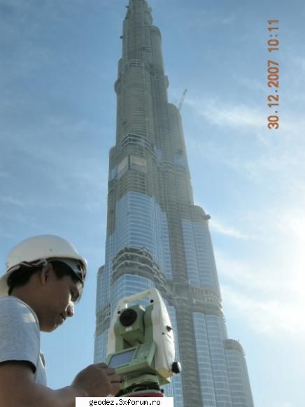
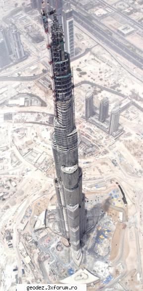
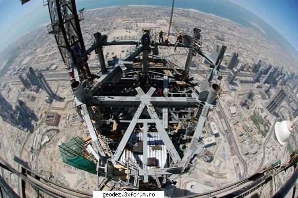
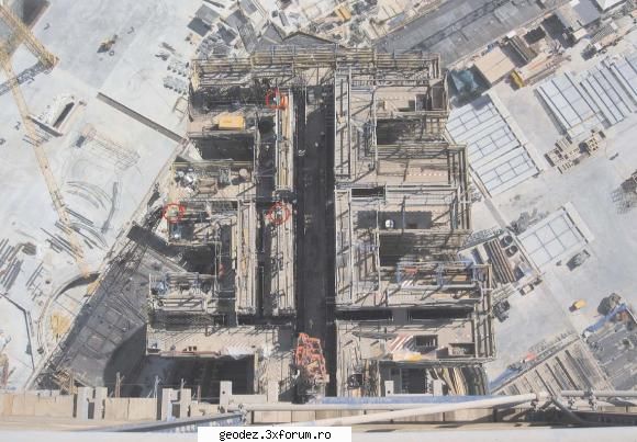
The Burj Dubai tower in Dubai, UAE, will rise to a height of over 800m when complete in 2008. In addition to being very tall it is also quite slender and it is anticipated that there will be movement of the building at upper levels due to wind loads, crane loads, construction sequence and other factors.
The self climbing formwork system for the building is complex, due to the shape of the structure and requires a large number of control points. It has been necessary to develop a survey system that can efficiently provide the large number of control points and can be used when the building is moving.
An analysis of predicted movements has been completed and a system installed which delivers accurate positioning for construction set out at the top level of the formwork.
Limited results are available to date but monitoring indicates that the required accuracy is being achieved.
1.2Building Movements
The various components resulting in the displacement and motion of the structure can be divided in to three groups.
1.2.1Long Period Movements
These components may cause movement in the tower in a period of from one week to 6 months.
* Uneven Raft Settlement. As the load on the raft foundation increases it will continue to settle and if the settlement is uneven this will cause a corresponding tilt in the tower structure.
* Raft Deformation. Due to the greater load at the centre of the tower the raft foundation will deform as construction progresses and this deformation may affect the verticality of the structure.
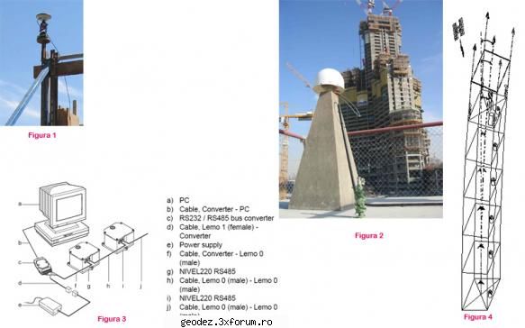
* Construction Sequence. Construction is progressing in a circular sequence on a 5 - 7 day cycle for each level and this will cause the centre of mass of the building to move from the vertical axis and may cause a corresponding movement in the structure. Refer Figure 3.
* Building Design. The design of the building, with the set back on wings occurring at different levels introduces a movement of the centre of mass in the building as it rises and the final position of the theoretical design shape is offset from the vertical axis. This may cause a movement in the tower position which is closely linked with the construction sequence.
* Concrete Creep and Shrinkage. Long term, differential, creep and shrinkage in the tower columns may cause the tower centre to move by small amounts over a long period. The amount of deflection will depend on the level at which the differential shortening develops.
1.2.2Daily Movements
This component may cause movement in the tower over a 24 hour period.
Solar Effects . The concrete surfaces exposed to the sun will expand when compared to those on the opposite side of the building. This will result in the building moving away from the sun. Mathematical modelling of solar effects on the structure indicate that with a temperature differential of ten degrees centigrade a movement of up to 150mm at the top of the concrete is possible over a six hour period. This equates to a movement of 25mm per hour at that level. Most of the control for the formwork needs to be set during the day when the solar effect will be at a maximum.
1.2.3Dynamic Movements
These components cause movement in the tower with periods of as little as 10 seconds up to 15 minutes
* Building Resonance. According to information from the structural engineers the building will have a natural period of 10 to 11 seconds in two axis which if the position data is computed at say every 0.5 seconds then the shape of a point plot of 30 minutes of data would resemble an irregular ellipse. If wind speed increases then the size of this ellipse would also increase.
* Wind Drag. Wind loads will cause the building to move off centre by amounts which are dependant on wind speed, direction and structural factors.
* Crane Loads. It is anticipated that the building will move to some extent when a tower crane picks up or releases a load. These movements will be completely random with periods of 5 to 15 minutes. When positioning surveys are being carried out it will be necessary to shut down the cranes to reduce the chances of a random bias in the measurement of the displacement.
The loads and other effects on the tower will cause it to move from the theoretical vertical axis and the natural building resonance will cause it to oscillate about this offset position. The survey system had to be designed to tolerate this movement and allow construction to proceed in a continuation of the alignment of the previous levels.
1.3Formwork System
The formwork for each concrete pour is comprised of a series of individual forms which all require control. This has resulted in 240 control points for the formwork system for each level.
It was not practical or safe to use the traditional method of plumbing up through floor penetrations and at the beginning of the project it was decided to use resection as the primary procedure for survey control.
1.4Initial Surveys
At contract commencement six permanent bench marks were established around the site and precisely surveyed. These marks consisted of a concrete encased steel I beam extending down to about 15m below ground level. A cap was cast at the top to provide a solid work platform. These marks were used for all the initial set out surveys and as a base for the monitoring work.
1.4.1Lower Levels
Due to the large number of control points required for the formwork it was necessary to develop a method so that the control was only measured once. The only solid part of the building is the concrete and the technique sets marks in the top surface of the newly cast concrete.
A total station instrument is also set up on the concrete and position established by resection to the external bench marks. The marks set in the top surface are measured by radiation from this resected control position and the precise coordinates for each mark calculated.
When the formwork is raised to the next level the marks are offset onto the main working deck of the formwork which is tied in to the concrete at that position. The back of the shutters can then be positioned from these marks.
From ground to about Level 20 resection was possible from the external control marks which were distant about 100 to 150 m from the base of the tower. Observation redundancy was possible and very high quality results were achieved. Verticality observations confirmed that the tower was not moving and raft foundation measurements indicated there was no differential settlement to cause the tower to tilt. Hence it was a straight forward surveying task to set out control for the formwork using this method.
1.4.2Upper Levels
As the building rises it will come under the influence of various forces as described in 1.2 above and will start to move by varying amounts and sometimes in random directions.
Above Level 20 it became increasingly difficult to sight the external control on site due to obstruction from the upper decks of the formwork system. In Dubai the nearest tall, stable, buildings were over 500m distant from the site and could not be used because of potential visibility problems and poor geometry.
At this stage it became necessary to implement a new method of resection and a measurement system that could tolerate building movement. It was also necessary to install a means of measuring the building movement to ultimately identify any long term, permanent movement of the tower in a particular direction which might need to be counteracted.
2.CORE WALL SURVEY SYSTEM
The movement of the structure creates several problems for precise survey; at a particular instant in time, theoretically, you need to know exactly how much the design centre line of the building is offset from the vertical axis and at that same instant you need to know the precise coordinates of the instrument. However a mean position taken over a short period for both elements can provide a suitable solution.
2.1Instrument Position Determination
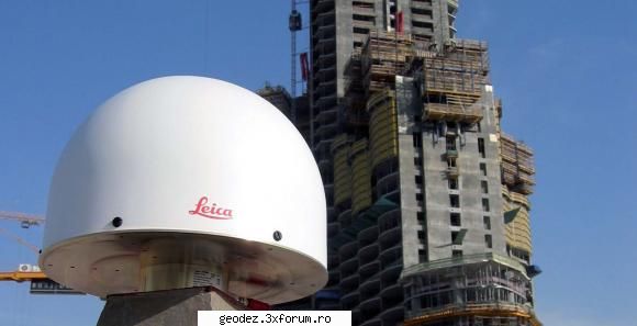
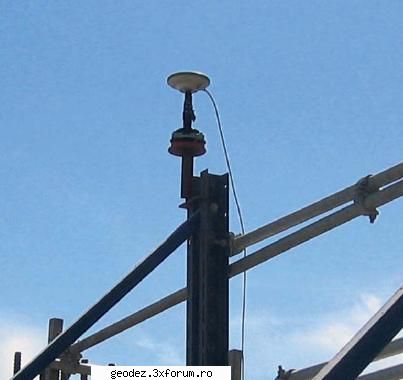
GPS operating in static mode are being used to establish survey control at the upper levels. The system comprises a minimum of 3 GPS antenna/ receivers mounted on tall fixed poles at the top level of the formwork.
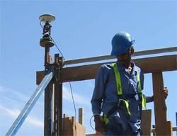
A tiltable circular prism is placed below each antenna and a Total Station instrument (TPS) is set up on the concrete visible to all GPS stations. The GPS plus TPS comprises a measurement system.
Figure 1: GPS and circular prism collocated
In static GPS mode, satellite signal data is received and recorded for a period of up to 1 hour. During this same period of time, the TPS instrument is used to measure a series of angles and distances to the prisms mounted below the GPS antennas. The TPS then measures to the reference marks placed on fresh concrete which are the reference points for control of the formwork as described in 1.4.1.
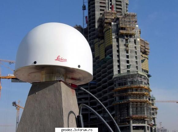
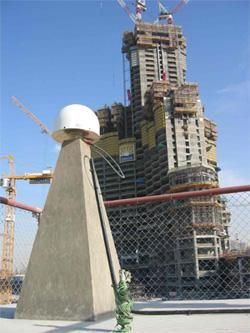
After completion of observations, data is returned to the office for processing. Computation of GPS antenna positions is carried out, processed against data from a Continuously Operating GPS Reference Station Leica GPS GRX1200 Pro with AT504 chokering antenna and Leica GPS Spider software, using Leica Geo Office software (LGO).
Figure 2: Continuous Operating Reference Station
Computation of TPS position is then carried out actually as a least squares resection. Finally transformation is performed of the 3 no WGS84 antenna coordinates and resected TPS coordinates into the local coordinate system and from this a determination of coordinates of all measured reference marks is made. These steps yield coordinates of survey instrumentation and reference marks in the site project coordinates.
A total station, or more generally any theodolite, can be considered as a dual axis system supporting the line of sight of a transit/telescope. For reducing the effect of the mechanical misalignments on the observations, classical operational procedures have been applied since the first use of such instruments. Today, a total station can take these axis misalignments into account using an inbuilt dual axis compensator and special firmware to correct the resulting error in the measurements. However, the operational range of the compensators is restricted, typically to about six minutes of arc. The operator aligns the main axis coarsely by keeping the bubble of the station inside the graduation. In case of a compensator out of range signal, the station must be realigned manually. This procedure known by experienced operators as simply inappropriate when operating a total station in this case when we expect dynamic behaviour and overal as we the building main axis will not be aligned with the direction of local gravity
To remove that restriction it will be necessary to consider this instrument as a local 3D axis system. The coordinates computed by using the observations (directions and distance) are internally consistent but must be transformed into the reference frame defined by the set of GPS antennas. In our case as we use a single total station, the problem is simply a 3D transformation also known as similarity transformation or Helmert transformation.
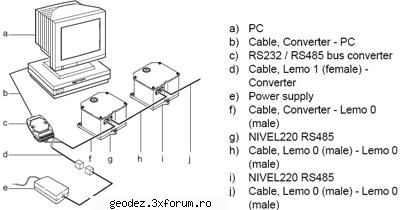
Figure 3: Tiltmeter to PC Connection
2.2Building Alignment Determination
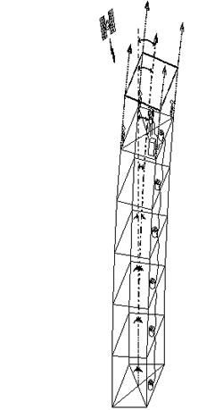
The Core Wall Survey System (CWSS) uses NIVEL200 dual-axis precise clinometers to accurately determine displacement of the tower alignment from vertical. Clinometers measure absolute tilt to +/-0.2 arc. This angular measure can be applied to the vertical distance of the clinometers sensor above the foundation raft to provide a computed plan displacement in X and Y at that elevation due to the tilt of the structure.
A total of 8 precise clinometers are to be networked at approximately every 20 floors up the tower as construction proceeds. Each instrument will be mounted in the center core wall in a boxout within the wall where casual disturbance is unlikely.
When the clinometers are installed initially they will be calibrated in relation to the survey control at that level by verticality observations from the raft foundation. A series of observations will provide a mean displacement in X and Y for that tilt meter at that time and will then be applied to all future readings so that the output will reflect the displacement of the tower alignment at that level in relation to the vertical axis.
Clinometers will be connected through an RS-485 single bus cable to the LAN port of a dedicated PC located at the survey office running Leica GeoMoS software.
Continuous, real-time measurements of structure tilt can be logged for each instrument floor, and data output as X and Y components of building alignment from the vertical. Amplitude peaks of smoothed data represent structure oscillations.
The mean displacement of the regression line represents total mean displacement of the structure. A block of data corresponding to the GPS observation data will be used for this purpose.
Differentiation of the tiltmeter data at different heights will allow correction for nonlinear structure tilt.
2.3Core Wall Survey System
The GPS Reference Station, the GPS receivers and antennas with circular prism, the Total Station are combined with the precise clinometers network as shown below composed the 4 measuring sub-elements of the complete data fusion system.
3.PRECISION
An examination of the likely errors in the CWSS indicates that it will be possible to continue to set out the formwork along the vertical alignment of the structure to a precision of ± 15mm.
Figure 4: Data Fusion System
8.ANALYSIS
Monitoring surveys will provide information on raft foundation settlement and deformation and this can be used to accurately determine the offset of the tower at a particular level due to the influence of these factors. Similarly surveys to measure the differential shrinkage and creep in the core walls and columns can be used to derive this possible component of tower movement.
A dynamic model of the building has been developed and from this it has been possible to derive values at any given level for the effects of construction sequence, building design and solar effects. For the period of the control survey if the tower cranes are shut down then the only remaining unknown component of building movement is that due to wind. Weather stations are to be established at three locations on the tower and these will stream continuous data on temperature, wind speed and direction. This can be correlated with the tilt meter data to determine a relationship. It is anticipated that this analysis will reveal any long term movements in a given direction and if necessary corrective action can be taken.
The Nivel200 Network segment of this system can be used for tower monitoring, both during construction and after completion of the structure. If this is integrated with other monitoring information it will provide a complete system of structure monitoring.
CONCLUSIONS
A combination of GPS survey techniques, Automatic Total Station, clinometers readings and mathematical modelling will provide a means to drive the construction of the worlds tallest building as a straight structural element and provided a wealth of data on building movement.
Its only the start of a long journey up to the final completion of the Burj Dubai tower and the authors know that they will have to complement the existing data fusion system with other elements the time being.
32KB
|
|